AIO Ceiling Ducted unit above a false ceiling

AIO Ceiling Ducted

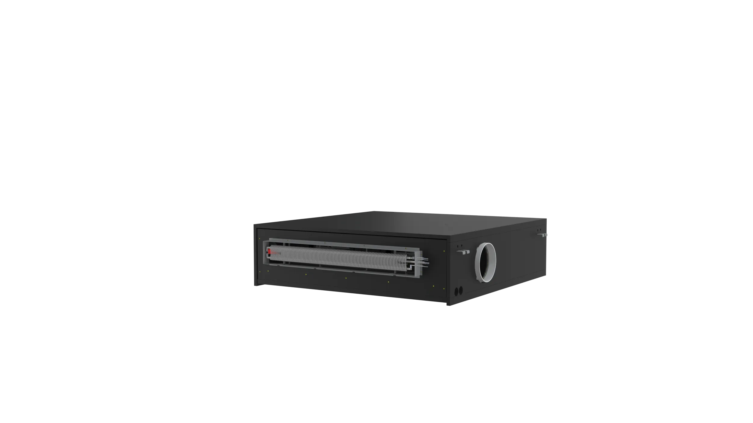
AIO Ceiling Ducted unit render

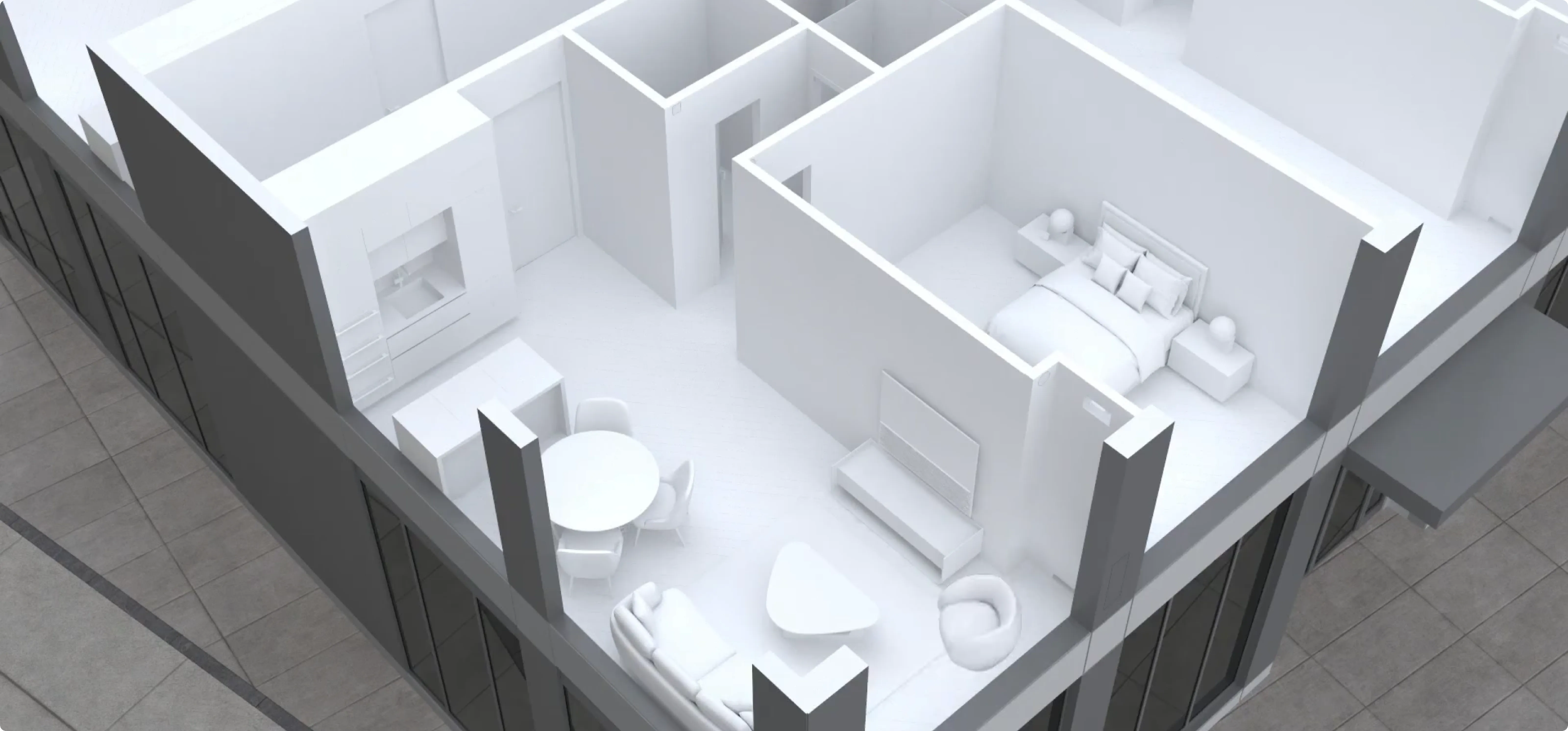
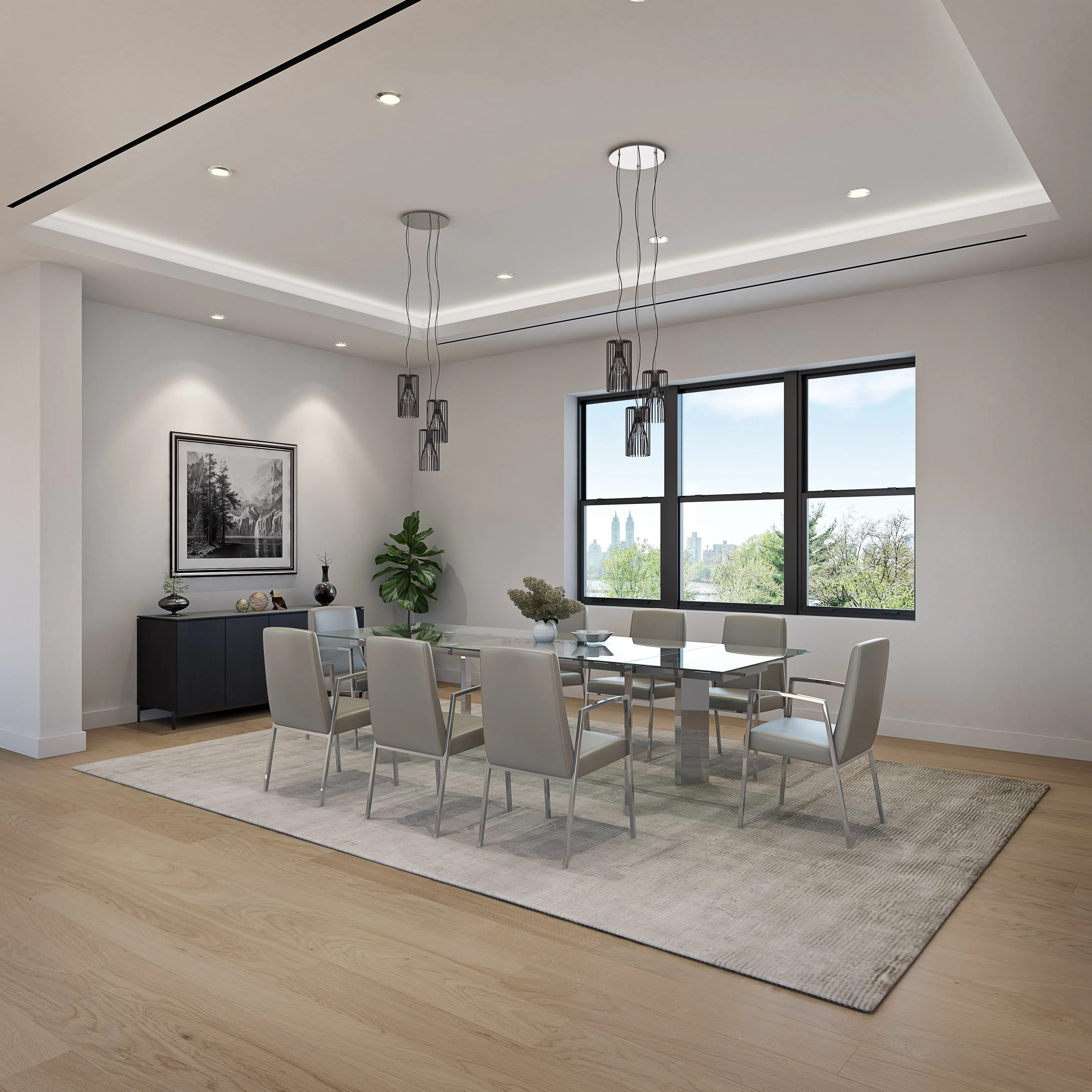
AIO Ceiling Ducted can be discreetly installed above a ceiling.

AIO Ceiling Ducted units install discreetly above a ceiling and are ideal for single or multi-room applications. The return can come from the sides or bottom for maximum flexibility. With up to 0.6" WC external static pressure, they work well where ducting is required. Pair with any interior grille and louver for added design flexibility, and connect a bathroom exhaust to the dedicated stale-air outlet. Available with or without integrated ERV.
Key Features

  • Compact unit
  • Easy to install
  • Paintable sleek cabinet
  • Auto-restart
  • Washable filters

Options

  • Optional 900 or 1,800W electric heat
  • With or without ERV
  • 115V or 230V
  • Hardwire or LCDI cord
  • R32

Operation

  • Cool, heat, dehumidify, and auto
  • Selectable fan speeds, low, med, high, and auto
  • Fresh air ERV - field configurable amount of fresh air

Mounting

  • Ceiling
  • Underfloor

Airflow

  • Dual 8' external vents
  • Available 0.7" WC for external ducting, adapters, and louvers
  • Available 0.6" WC for internal ducting and louvers

Included controls

  • Onboard touch controller for diagnostics and programing (on bottom of the unit)

Optional controllers

  • WiFi app for Android and iPhone
  • Wall Mounted Advanced touchscreen with a 7‑day program
  • Wall Mounted Basic touch controller
  • Third party thermostat interface
  • BACnet/Modbus interface

Airflow

AIO Ceiling Ducted is flexible in many ways. It can be fully ducted or used with minimal or no ducting. This flexibility enables AIO Ceiling Ducted to be placed anywhere in a dwelling without restrictions.

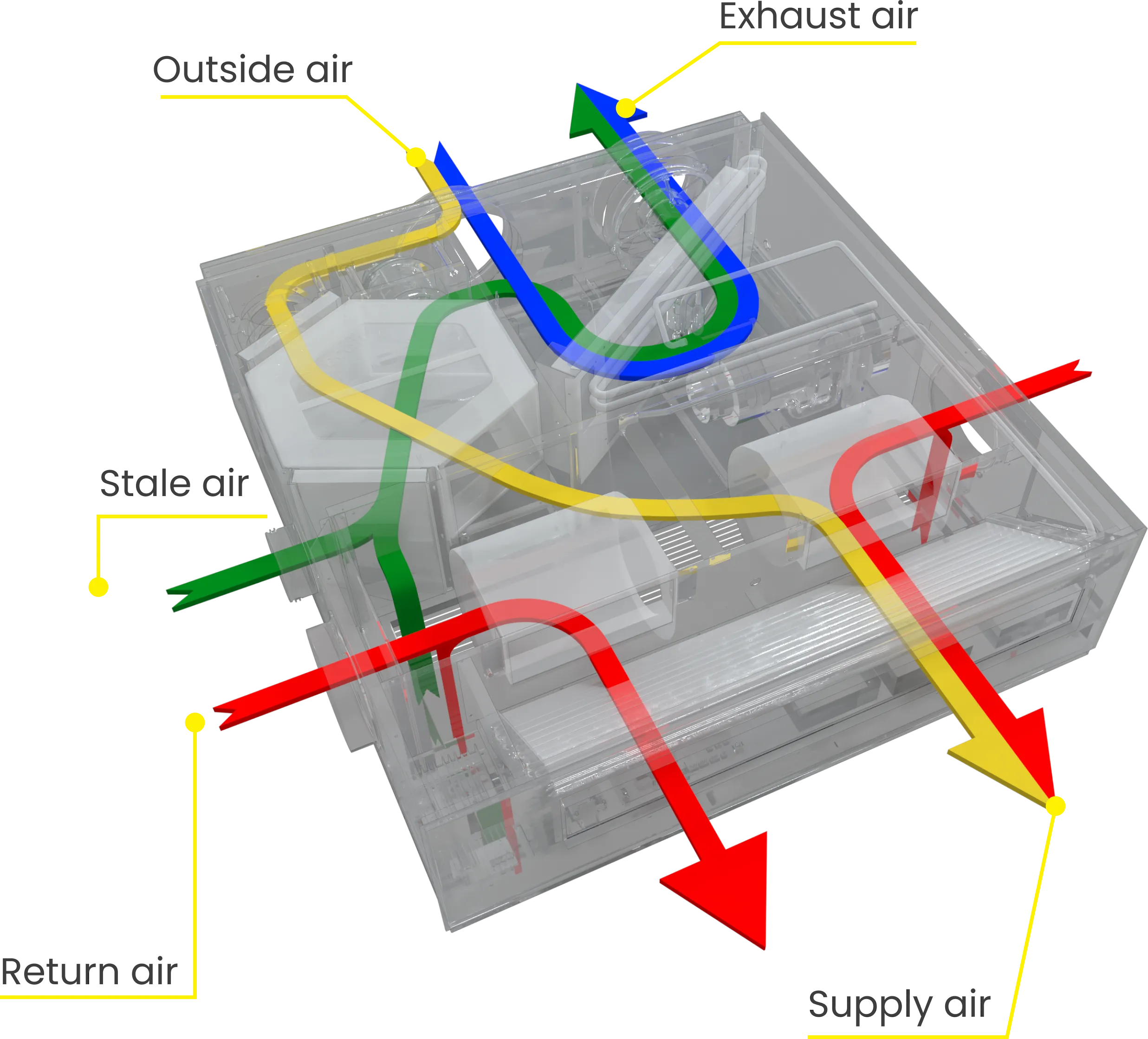
AIO Ceiling Ducted airflow diagram — side return configuration
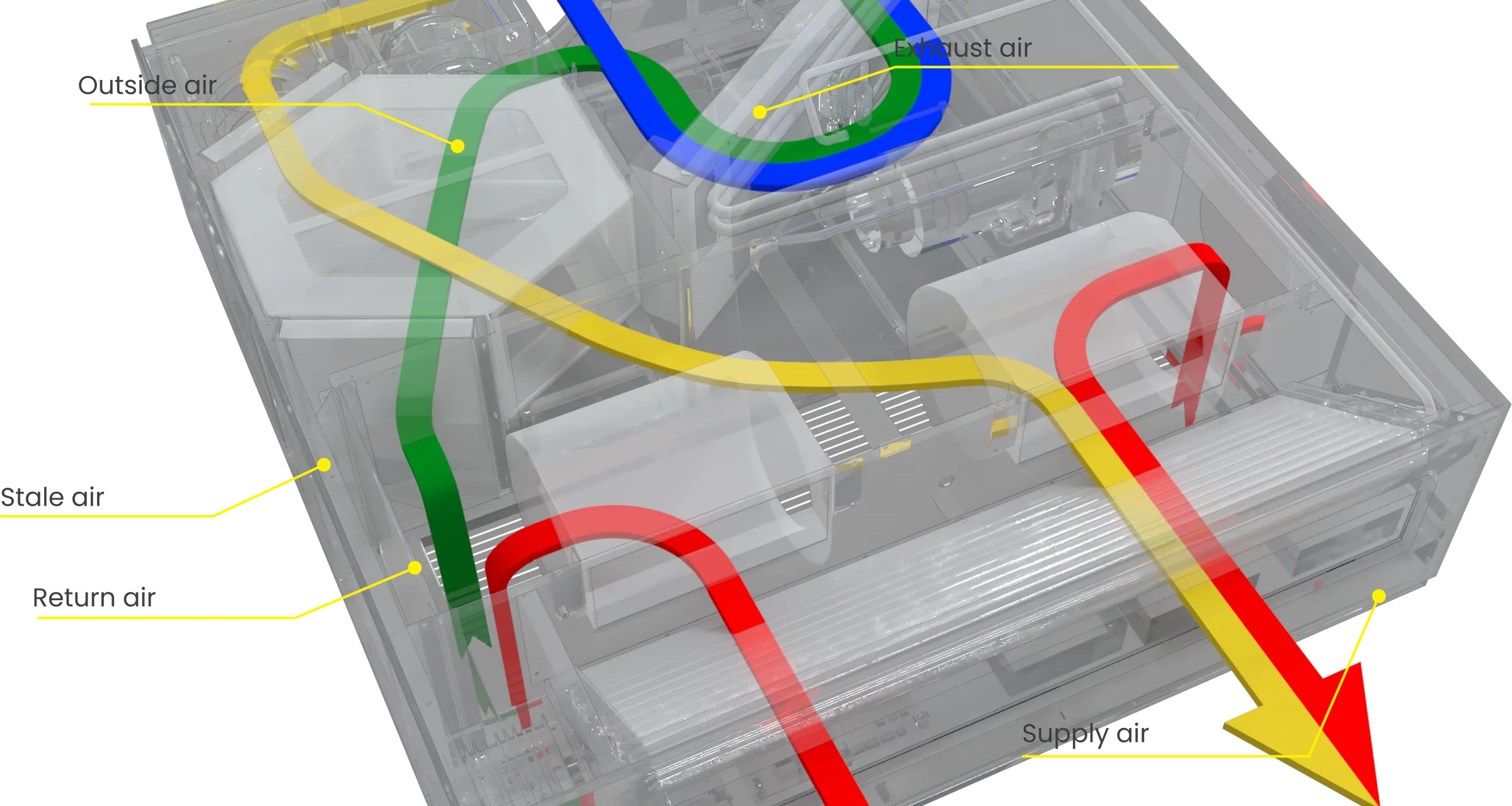
  • Outside air
  • Recirculate air
  • Fresh air intake
  • Stale air exhaust
AIO Ceiling Ducted airflow diagram — bottom return configuration

Installation

AIO Ceiling Ducted installation photo

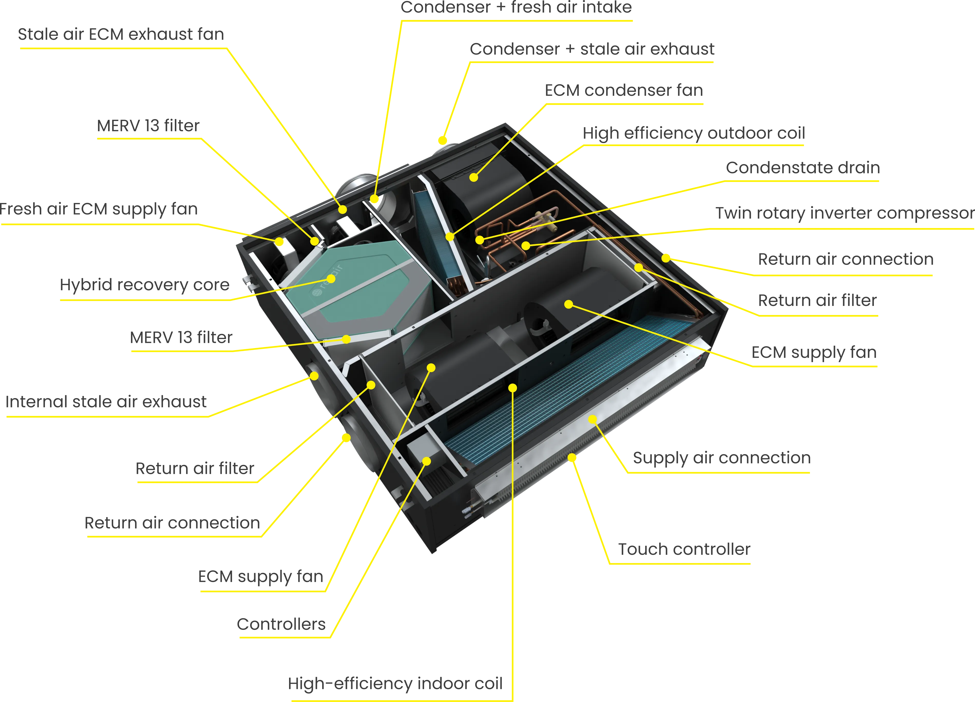
What's Inside

AIO Ceiling Ducted internal components diagram

Key Specifications

High Performance
Heat Pump only95°F¹105°F²115°F³
Capacity
Maximum (kBtu/h)15.011.49.8
Recommended (kBtu/h)*9.48.27.3
Nominal (kBtu/h)7.77.46.6
Minimum(kBtu/h)3.13.13.1
Power Input
Maximum (kW)1.581.641.70
Recommended (kW)*0.960.981.04
Nominal (kW)0.730.830.91
Minimum (kW)0.230.260.29
Efficiency
Maximum9.57.05.8
Recommended*9.88.47.0
Nominal10.68.97.3
SEER213.85--
Moisture removal (Pts/h)1.822.2
1
95°F
ID: 80°F, W.B. 67°F;
OD: 95°F, W.B. 75°F
2
105°F
ID: 80°F, W.B. 67°F;
OD: 105°F, W.B. 75°F
3
115°F
ID: 80°F, W.B. 67°F;
OD: 115°F, W.B. 75°F

* This is the recommended capacity for sizing the unit to the space

Heat Pump only**47°F¹17°F²5°F³0°F⁴-5°F⁵
Capacity
Maximum (kBtu/h)14.010.06.66.35.8
Recommended (kBtu/h)*9.29.36.25.95.6
Nominal (kBtu/h)8.68.36.25.95.6
Minimum(kBtu/h)3.53.32.82.53.3
Power Input
Maximum (kW)1.421.461.701.601.65
Recommended (kW)*0.780.991.251.061.01
Nominal (kW)0.700.861.091.061.01
Minimum (kW)0.320.420.440.430.48
Efficiency
Maximum2.92.01.11.11.0
Recommended3.52.81.51.61.6
Nominal3.62.81.71.61.6
Minimum3.32.31.91.72.0
HSPF29.2----
1
47°F
ID: 70°F, W.B. 60°F;
OD: 47°F, W.B. 43°F
2
17°F
ID: 70°F, W.B. 60°F;
OD: 17°F, W.B. 13°F
3
5°F
ID: 70°F, W.B. 60°F;
OD: 5°F, W.B. 3°F
4
0°F
ID: 70°F, W.B. 60°F;
OD: 0°F
5
-5°F
ID: 70°F, W.B. 60°F;
OD: -5°F

* This is the recommended capacity for sizing the unit to the space.

** The tables show Heat Pump performance only. An electric heating element can be added to provide an additional output of 3,100 or 6,100 BTU/h.

High Efficiency
Heat Pump only95°F¹105°F²115°F³
Capacity
Maximum (kBtu/h)15.011.49.8
Recommended (kBtu/h)*9.48.27.3
Nominal (kBtu/h)6.17.46.6
Minimum(kBtu/h)3.13.13.1
Power Input
Maximum (kW)1.581.641.70
Recommended (kW)*0.960.981.04
Nominal (kW)0.530.830.91
Minimum (kW)0.230.260.29
Efficiency
Maximum9.57.05.8
Recommended*9.88.47.0
Nominal11.68.97.3
SEER215.3--
Moisture removal (Pts/h)1.822.2
1
95°F
ID: 80°F, W.B. 67°F;
OD: 95°F, W.B. 75°F
2
105°F
ID: 80°F, W.B. 67°F;
OD: 105°F, W.B. 75°F
3
115°F
ID: 80°F, W.B. 67°F;
OD: 115°F, W.B. 75°F

* This is the recommended capacity for sizing the unit to the space

Heat Pump only**47°F¹17°F²5°F³0°F⁴-5°F⁵
Capacity
Maximum (kBtu/h)14.010.06.66.35.8
Recommended (kBtu/h)*9.28.76.25.95.6
Nominal (kBtu/h)8.67.86.25.95.6
Minimum(kBtu/h)3.53.32.82.53.3
Power Input
Maximum (kW)1.421.461.701.601.65
Recommended (kW)*0.780.991.251.061.01
Nominal (kW)0.700.861.091.061.01
Minimum (kW)0.320.420.440.430.48
Efficiency
Maximum2.91.11.11.11.0
Recommended3.52.81.51.61.6
Nominal3.82.81.81.61.6
Minimum3.33.01.91.72.0
HSPF29.2----
1
47°F
ID: 70°F, W.B. 60°F;
OD: 47°F, W.B. 43°F
2
17°F
ID: 70°F, W.B. 60°F;
OD: 17°F, W.B. 13°F
3
5°F
ID: 70°F, W.B. 60°F;
OD: 5°F, W.B. 3°F
4
0°F
ID: 70°F, W.B. 60°F;
OD: 0°F
5
-5°F
ID: 70°F, W.B. 60°F;
OD: -5°F

* This is the recommended capacity for sizing the unit to the space.

** The tables show Heat Pump performance only. An electric heating element can be added to provide an additional output of 3,100 or 6,100 BTU/h.

Documentation

Bottom Return Configuration

Ceiling Ducted - Mirror Version

Data Sheet

Shroud extension

Rough-In Casing

Data Sheet

Trusted by leading brands worldwide

Certified by Leading HVAC Industry Associations