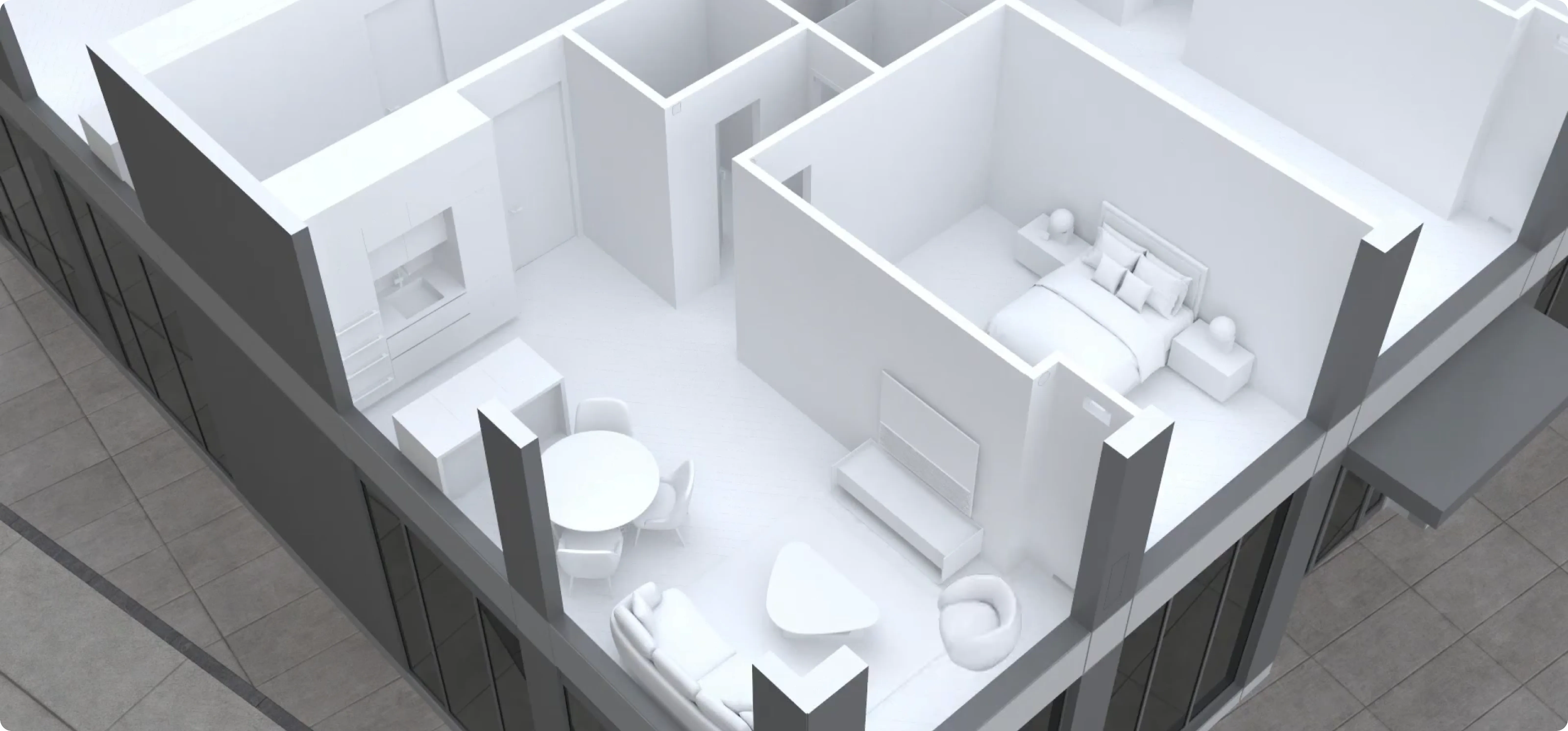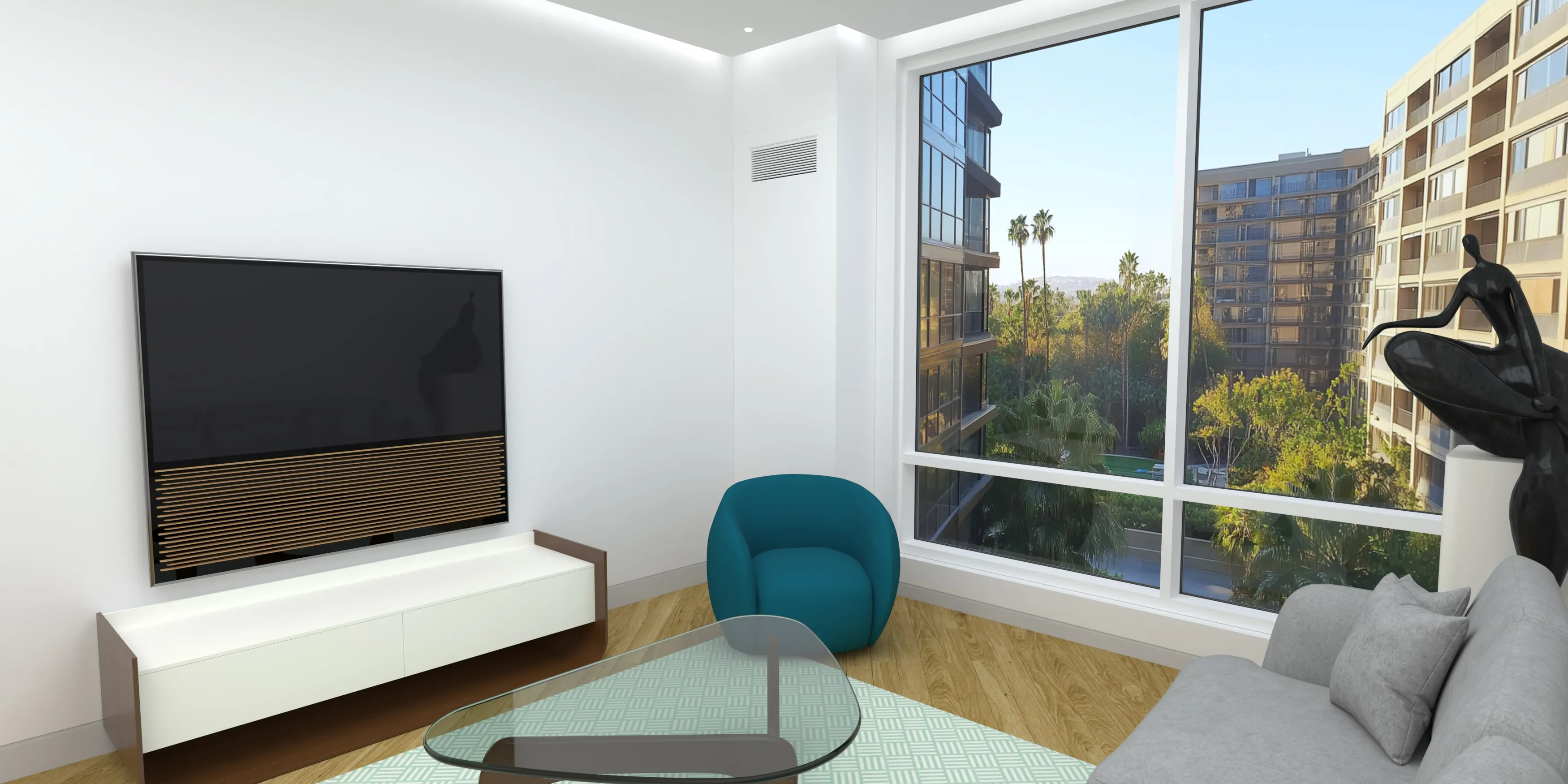
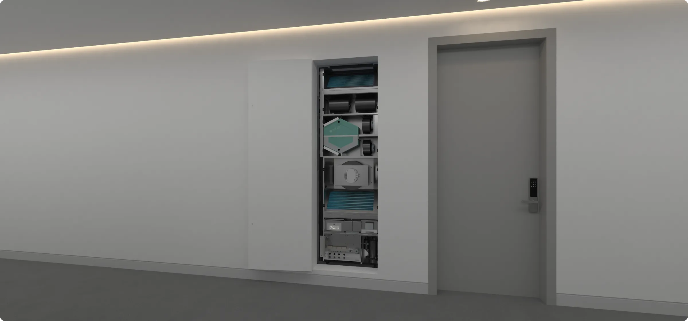
AIO Vertical Stack unit in a corridor wall

AIO Vertical Stack

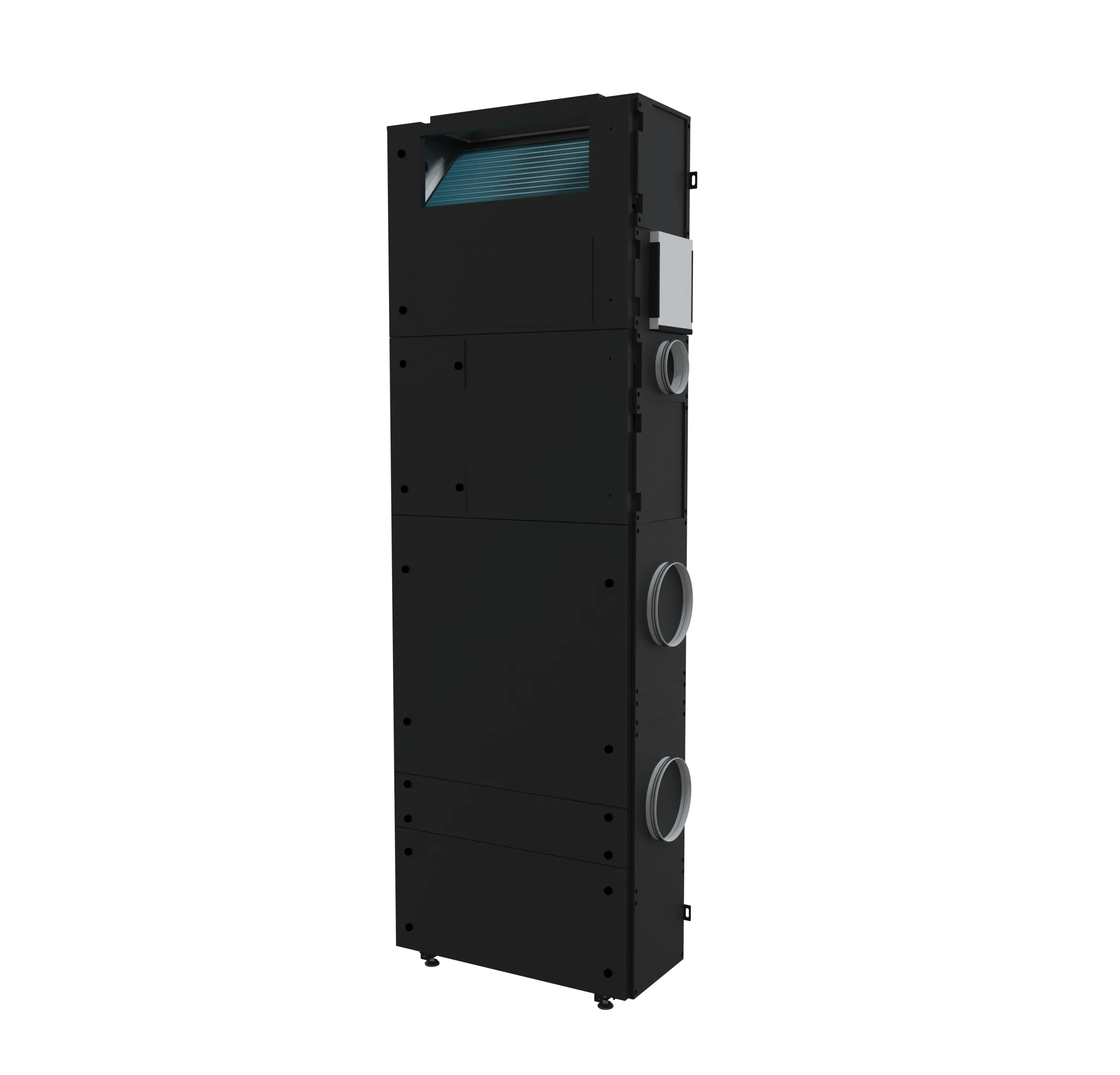
AIO Vertical Stack unit render

AIO Vertical Stack is the ideal multi-room solution.

The AIO Vertical Stack is the ideal multi-room solution when a ceiling unit isn't feasible. Its compact 12" x 25" footprint saves floor space and delivers up to 0.6" WC static pressure for direct venting or ducting. A unique feature: it installs on a corridor wall for full servicing without entering the room. A bathroom exhaust connects to the dedicated stale-air outlet (field-adjustable left or right). Available with or without integrated ERV, venting outside or through ductwork.
Key Features

  • Compact unit
  • Easy to install
  • High ESP for internal and external ducting
  • Extraordinary flexible ducting
  • Bathroom exhaust connection
  • Auto-restart
  • Washable filters

Options

  • Optional 900 or 1,800W electric heat
  • With or without ERV
  • 115V or 230V
  • Hardwire or LCDI cord
  • R32
  • MERV 13 filtration on return air

Operation

  • Cool, heat, dehumidify, and auto
  • Selectable fan speeds, low, med, high, and auto
  • Fresh air ERV - field configurable amount of fresh air (with optional ERV Module)

Mounting

  • Vertical

Airflow

  • Dual 8' external vents
  • Available 0.7" WC for external ducting, adapters, and louvers
  • Available 0.6" WC for internal ducting and louvers

Included controls

  • Onboard touch controller for diagnostics and programing

Optional controllers

  • WiFi app for Android and iPhone
  • Wall Mounted Advanced touchscreen with a 7‑day program
  • Wall Mounted Basic touch controller
  • Third party thermostat interface
  • BACnet/Modbus interface

Airflow

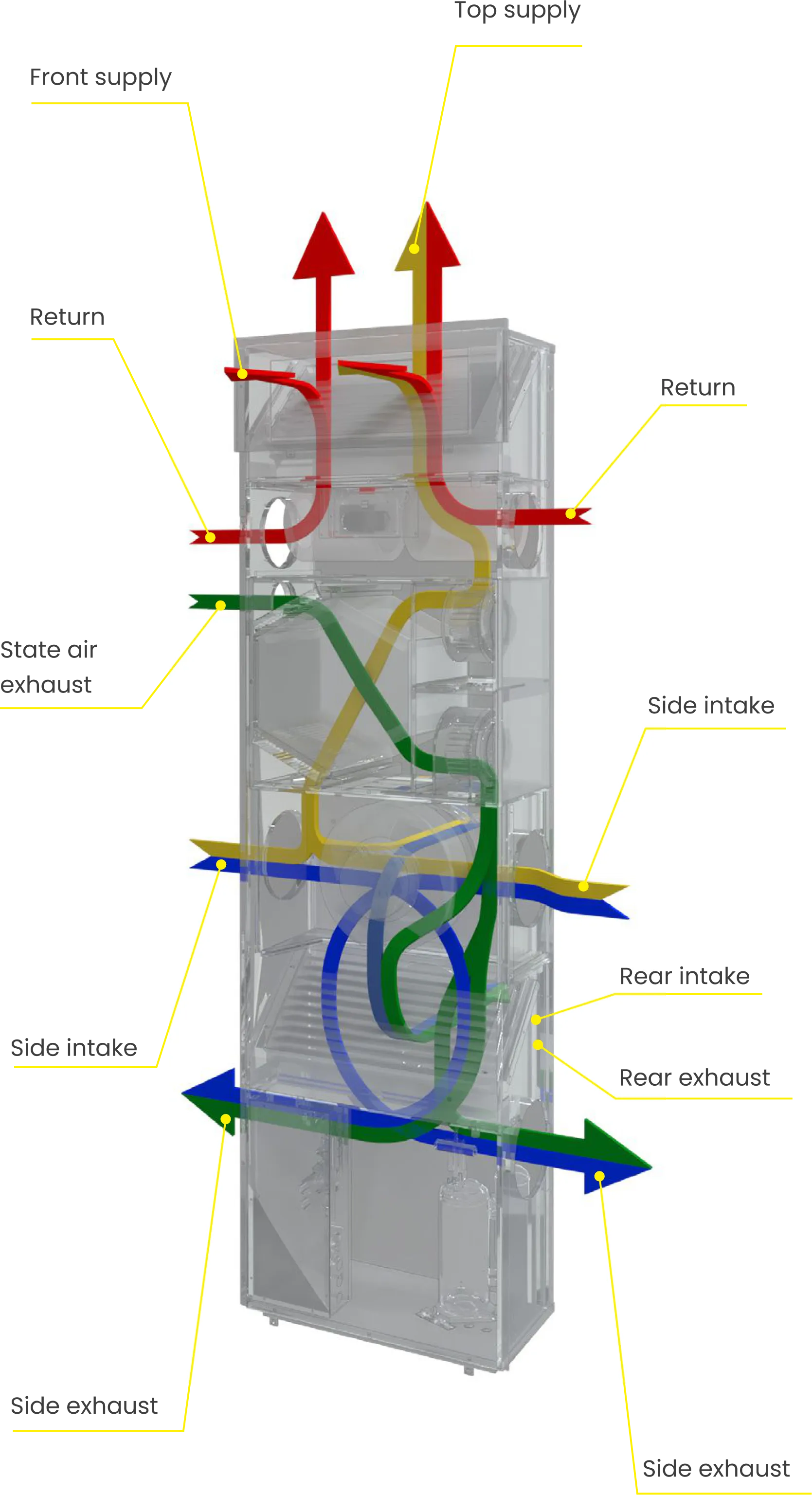
AIO Vertical Stack is extraordinarily flexible in the many ways it can be fully ducted or used with minimal or no ducting. This flexibility enables Vertical Stack to be placed anywhere in a dwelling with no restrictions.

AIO Vertical Stack airflow diagram
  • Outside air
  • Recirculate air
  • Fresh air intake
  • Stale air exhaust

Stale air exhaust

The five-inch round stale air exhaust connection can be used as part of a plenum return without any ducting or can be ducted to a bathroom or multiple locations with up to 0.5” WC external static pressure. If configuring AIO Ceiling Ducted with a bottom return, the stale air can also be pulled from the bottom return.

Outside air intake

The single 8” round outside air intake connection provides air for the condenser portion and fresh air for the inside. This can be ducted with up 0.7” WC external static pressure (combined between intake and exhaust).

Outside air exhaust

The single 8” round outside air exhaust connection is for the condenser portion and the stale air exhaust. This can be ducted with up 0.7” WC external static pressure (combined between intake and exhaust).

Return air – bottom option

The bottom 8.7” x 22” return is designed to be used with a ceiling-mounted return grille or an access panel with an integrated return grille.

Return air – sides options

The left and right side 6” round connection can be ducted to one or more rooms with up to 0.6” external static pressure (combined between return and supply). It can also be left open as a side plenum return. Each connection is fully independent with two ECM fans, each with auto ESP. Duct both, leave both open or duct one, and leave one open to a plenum.

Supply air

The rectangular 4” x 29” supply air connection is ideal for a supply grille or ducting, with up to 0.6” external static pressure (combined between return and supply).

No Access Required

The versatile design of AIO makes the system extremely reliable and inexpensive to maintain. If a repair is needed, a single unit can be taken off-line without affecting the entire system. It's possible to install AIO Vertical stack on the corridor wall of each apartment/hotel room so that all maintenance can be achieved from a common area - at any time, which means no maintenance personnel needs to enter the unit.

AIO Vertical Stack serviced from the corridor — no room access required

Installation

AIO Vertical Stack installation photo

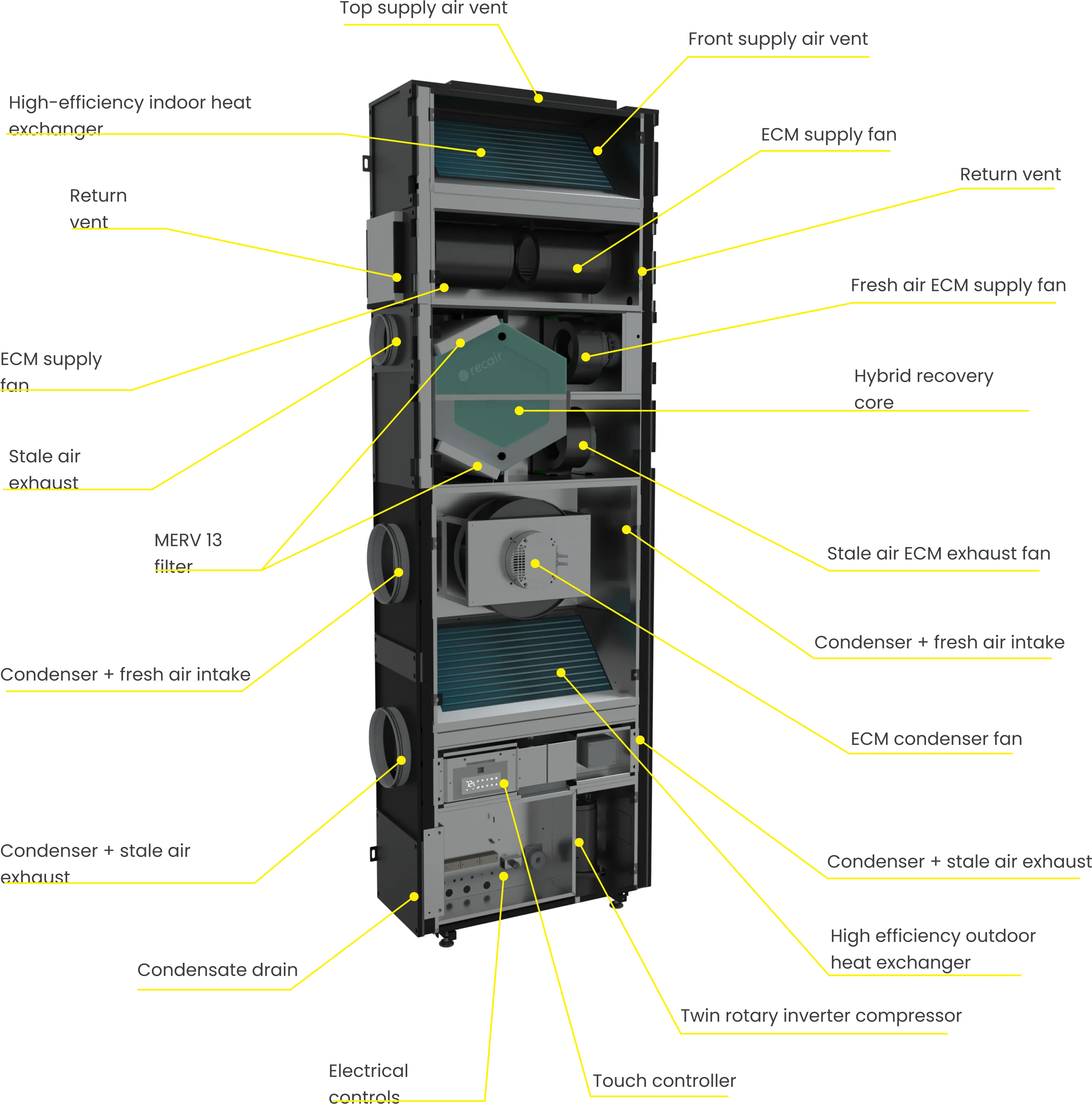
What's Inside

AIO Vertical Stack internal components diagram

Key Specifications

High Performance
Heat Pump only95°F¹105°F²115°F³
Capacity
Maximum (kBtu/h)14.413.111.8
Recommended (kBtu/h)*9.88.57.8
Nominal (kBtu/h)8.97.66.9
Minimum(kBtu/h)3.63.63.4
Power Input
Maximum (kW)1.751.681.06
Recommended (kW)*0.960.971.10
Nominal (kW)0.810.850.93
Minimum (kW)0.250.280.30
Efficiency
Maximum8.237.86.74
Recommended*10.278.87.4
Nominal11.019.07.47
SEER214.35--
Moisture removal (Pts/h)1.822.2
1
95°F
ID: 80°F, W.B. 67°F;
OD: 95°F, W.B. 75°F
2
105°F
ID: 80°F, W.B. 67°F;
OD: 105°F, W.B. 75°F
3
115°F
ID: 80°F, W.B. 67°F;
OD: 115°F, W.B. 75°F

* This is the recommended capacity for sizing the unit to the space

Heat Pump only**47°F¹17°F²5°F³0°F⁴-5°F⁵
Capacity
Maximum (kBtu/h)13.89.46.76.46.0
Recommended (kBtu/h)*10.09.06.56.16.5
Nominal (kBtu/h)8.99.06.56.15.8
Minimum(kBtu/h)8.33.32.82.72.7
Power Input
Maximum (kW)1.751.751.751.651.70
Recommended (kW)*0.761.151.111.081.19
Nominal (kW)0.661.151.111.081.03
Minimum (kW)0.420.440.460.480.50
Efficiency
Maximum2.311.571.121.141.03
Recommended13.22.31.721.675.5
Nominal3.812.301.721.671.64
Minimum2.722.21.781.651.58
HSPF29.8----
1
47°F
ID: 70°F, W.B. 60°F;
OD: 47°F, W.B. 43°F
2
17°F
ID: 70°F, W.B. 60°F;
OD: 17°F, W.B. 13°F
3
5°F
ID: 70°F, W.B. 60°F;
OD: 5°F, W.B. 3°F
4
0°F
ID: 70°F, W.B. 60°F;
OD: 0°F
5
-5°F
ID: 70°F, W.B. 60°F;
OD: -5°F

* This is the recommended capacity for sizing the unit to the space.

** The tables show Heat Pump performance only. An electric heating element can be added to provide an additional output of 3,100 or 6,100 BTU/h.

High Efficiency
Heat Pump only95°F¹105°F²115°F³
Capacity
Maximum (kBtu/h)14.413.111.8
Recommended (kBtu/h)*9.88.57.8
Nominal (kBtu/h)8.97.66.9
Minimum(kBtu/h)3.63.63.4
Power Input
Maximum (kW)1.751.681.75
Recommended (kW)*0.960.971.10
Nominal (kW)0.810.850.93
Minimum (kW)0.250.280.30
Efficiency
Maximum8.237.86.74
Recommended*10.278.87.4
Nominal11.019.07.47
SEER214.35--
Moisture removal (Pts/h)1.822.2
1
95°F
ID: 80°F, W.B. 67°F;
OD: 95°F, W.B. 75°F
2
105°F
ID: 80°F, W.B. 67°F;
OD: 105°F, W.B. 75°F
3
115°F
ID: 80°F, W.B. 67°F;
OD: 115°F, W.B. 75°F

* This is the recommended capacity for sizing the unit to the space

Heat Pump only**47°F¹17°F²5°F³0°F⁴-5°F⁵
Capacity
Maximum (kBtu/h)13.89.46.76.46.0
Recommended (kBtu/h)*10.09.06.56.16.5
Nominal (kBtu/h)8.99.06.56.15.8
Minimum(kBtu/h)8.33.32.82.72.7
Power Input
Maximum (kW)1.751.751.751.651.70
Recommended (kW)*0.761.151.111.081.19
Nominal (kW)0.661.151.111.081.03
Minimum (kW)0.420.440.460.480.50
Efficiency
Maximum2.311.571.121.141.03
Recommended13.22.31.721.675.5
Nominal3.812.301.721.671.64
Minimum2.722.21.781.651.58
HSPF29.8----
1
47°F
ID: 70°F, W.B. 60°F;
OD: 47°F, W.B. 43°F
2
17°F
ID: 70°F, W.B. 60°F;
OD: 17°F, W.B. 13°F
3
5°F
ID: 70°F, W.B. 60°F;
OD: 5°F, W.B. 3°F
4
0°F
ID: 70°F, W.B. 60°F;
OD: 0°F
5
-5°F
ID: 70°F, W.B. 60°F;
OD: -5°F

* This is the recommended capacity for sizing the unit to the space.

** The tables show Heat Pump performance only. An electric heating element can be added to provide an additional output of 3,100 or 6,100 BTU/h.

Documentation

Trusted by leading brands worldwide

Certified by Leading HVAC Industry Associations